Mounting instructions Mounting to the heat sink
Surface Requirements
To ensure a good contact and thermal conductivity between module and heat sink the following points must to
be considered:
- Surfaces of the module and the heat sink have to be free from any impurities, residues and particles which
may come from the thermal grease, from heat sink machining or from package materials.
- Heat sink fl atness in the mounting area to be ≤ 50μm per 100mm (according to DIN EN ISO 1101)
- Heat sink roughness RZ to be ≤ 10 μm (measured according to DIN EN ISO 4287)
- No steps on heat sink surface > 10 μm (measured according to DIN EN ISO 4287)
Note:
In case of natural convection cooling, the heat sink fi ns must be arranged so that the air can fl ow freely
from the bottom to the top. In case of forced convection cooling by air or liquid, the module can be moun-
ted in any position as long as the amount of the cooling medium is suffi cient for the load.
Mounting technique, examples
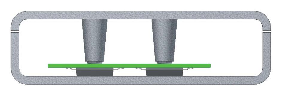
ISOPLUS-SMPD modules are a combination of a package which can be used in a PCB assembly in the style
of standard SMD components and power semiconductors which need to be mounted on a heat sink.
This leads to the question about a proper mounting method.
The module(s) should be soldered to the PCB fi rst and then the thermal grease would be applied to either the
module or the heat sink. Then the PCB including the module(s) needs to be assembled to the heat sink.
It is mandatory to ensure that DCB (module base) and heat sink surfaces are parallel to each other.
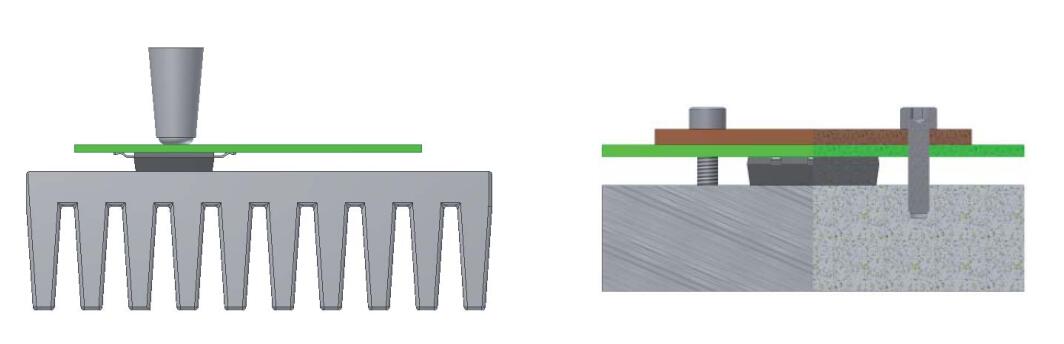
Fig. 7 shows examples for different assembly designs.
To prevent mechanical stress to leads of the device or the connections between the device and the PCB additi-
onal support from the heat sink to the PCB might be necessary.
ISOPLUS-SMPD modules are a combination of a package which can be used in a PCB assembly in the style
of standard SMD components and power semiconductors which need to be mounted on a heat sink.
This leads to the question about a proper mounting method.
The module(s) should be soldered to the PCB fi rst and then the thermal grease would be applied to either the
module or the heat sink. Then the PCB including the module(s) needs to be assembled to the heat sink.
It is mandatory to ensure that DCB (module base) and heat sink surfaces are parallel to each other.
Fig. 7 shows examples for different assembly designs.
To prevent mechanical stress to leads of the device or the connections between the device and the PCB additi-
onal support from the heat sink to the PCB might be necessary.
Mounting force
As mentioned above the thermal resistance of the whole system is signifi cantly affected by the interface from
module back side (DCB) to the heat sink. Besides the application of the right amount of thermal grease the
pressure is an important criterion for a good contact between the two surfaces and with it for a low thermal
resistance.
The mounting force should be in a range of 50N to 130N.
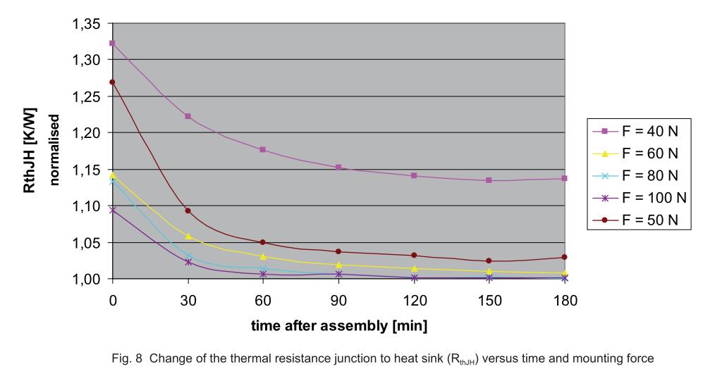
It is known that the thermal resistance of this interface is improving over time (Fig. 8). After mounting of the
device the thermal grease needs time to spread and squeeze out part of the grease which is not necessary to
provide a good contact.
This effect can be accelerated at elevated temperatures or using initially a higher pressure during the assem-
bly. This allows reducing the mounting force in the fi nal setup. Fig. 9 shows the dependency of the thermal
resistance versus the mounting force. First the pressure was increased step by step; one can see how the ther-
mal resistance is getting lower. Then the pressure was reduced again step by step but the thermal resistance
remains low over a wide range.
As mentioned above the thermal resistance of the whole system is signifi cantly affected by the interface from
module back side (DCB) to the heat sink. Besides the application of the right amount of thermal grease the
pressure is an important criterion for a good contact between the two surfaces and with it for a low thermal
resistance.
The mounting force should be in a range of 50N to 130N.
It is known that the thermal resistance of this interface is improving over time (Fig. 8). After mounting of the
device the thermal grease needs time to spread and squeeze out part of the grease which is not necessary to
provide a good contact.
This effect can be accelerated at elevated temperatures or using initially a higher pressure during the assem-
bly. This allows reducing the mounting force in the fi nal setup. Fig. 9 shows the dependency of the thermal
resistance versus the mounting force. First the pressure was increased step by step; one can see how the ther-
mal resistance is getting lower. Then the pressure was reduced again step by step but the thermal resistance
remains low over a wide range.
FOR MORE information about PCB assembly eepcb is the China leader PCB assembly services provider.
